An optimal ISA for teaching
In late 2021, a course convener that I had worked under before on other courses offered me a job to help radically redesign a course from the ground up. This course was on computer architecture, and the goal was for students to build a CPU from scratch, treating logic gates as the smallest atomic unit1. Instead of taking an off-the-shelf existing ISA, or implementing a subset of ARM or 8086 which is often done, we decided to built something bespoke: QuAC2, a CPU optimized specifically for the goal of being relatively simple to construct in hardware3 while still being a reasonable ISA for writing programs in, leaving a lot of room for extensions. This is a post-mortem of the machine, with some colour commentary of what I would have done differently, and design decisions that were made.
This make-believe CPU is still used in COMP2300 today, so I’ll avoid any spoilers for details on constructing the machine, but focus on the trade-offs made when we designed the machine.
The full ISA spec is on the course website, though I’ve replicated it here for convenience. The newest ISA might be slightly different as they shuffle things around so you can’t just use a solution from a previous year.
QuAC ISA (Click to expand)
QuAC ISA
Registers
All registers start initalised to 0x0000, and are 16-bits wide.
| Code | Mnemonic | Meaning | Behaviour |
|---|---|---|---|
| 000 | rz |
Zero Register | Always read zero, writes have no effect. |
| 001 | r1 |
Register 1 | General purpose register. |
| 010 | r2 |
Register 2 | General purpose register. |
| 011 | r3 |
Register 3 | General purpose register. |
| 100 | r4 |
Register 4 | General purpose register. |
| 101 | fl |
Flag register | Stores the flags from ALU whenever an ALU instruction is executed. Any operation can read this register. Write is undefined. |
| 110 | - | undefined | Any operation with this register is undefined. |
| 111 | pc |
Program Counter | General purpose register. Also stores the address of the current instruction being executed, and (unless the current instruction would overwrite it) is incremented to the next address after the current instruction is executed. |
rzis the zero register. Reading from the zero register returns the value0x0000. Writing to the zero register has no effect.4
-
r1,r2,r3, andr4are the general purpose registers. You may write to them, and they will store a value. Reading from a general purpose register returns the last value written to them. -
flis the flag register, which stores the flags generated by the last successfully executed ALU operation. The flag register may be read from like any other general purpose register. Writing to the flag register is undefined behaviour.5 -
pcis the program counter. It stores the address of the current instruction being executed. After an instruction is executed, the program counter is incremented (pc := pc+1) unless thepcwould be overwritten by the current instruction being executed.6 The program counter can be read from and written to like any other general purpose register.
Hardware Instructions
| Syntax | Semantic | Machine Code |
| I-Mode Instructions | ||
movl{z} rd, imm8
|
rd := #imm8
|
0000 z<rd> <imm8>
|
seth{z} rd, imm8
|
See below | 0001 z<rd> <imm8>
|
-
|
-
|
0010 xxxx xxxx xxxx
|
-
|
-
|
0011 xxxx xxxx xxxx
|
| R-Mode Memory Instructions | ||
str{z} rd, [ra]
|
[ra] := rd
|
0100 z<rd> 0<ra> 0000
|
ldr{z} rd, [ra]
|
rd := [ra]
|
0101 z<rd> 0<ra> 0000
|
-
|
-
|
0110 xxxx xxxx xxxx
|
-
|
-
|
0111 xxxx xxxx xxxx
|
| R-Mode ALU Instructions | ||
add{z} rd,ra,rb
|
rd := ra+rb
|
1000 z<rd> 0<ra> 0<rb>
|
sub{z} rd,ra,rb
|
rd := ra-rb
|
1001 z<rd> 0<ra> 0<rb>
|
and{z} rd,ra,rb
|
rd := ra&rb
|
1010 z<rd> 0<ra> 0<rb>
|
orr{z} rd,ra,rb
|
rd := ra|rb
|
1011 z<rd> 0<ra> 0<rb>
|
-
|
-
|
1100 xxxx xxxx xxxx
|
-
|
-
|
1101 xxxx xxxx xxxx
|
-
|
-
|
1110 xxxx xxxx xxxx
|
-
|
-
|
1111 xxxx xxxx xxxx
|
seth moves an 8-bit constant (imm8) into the high byte of the destination register rd, leaving
the low byte of rd unchanged. Formally, rd = (#imm8 << 8) | (rd & 0xff).
Instruction Encoding
Each instruction in QuAC has one of two formats, Register Operands Format (R-Mode) or Immediate Format (I-Mode).7
Register Operands Format (R-Mode)
op
|
z |
rd |
0 |
ra |
0 |
rb |
|||||||||
| 15 | 14 | 13 | 12 | 11 | 10 | 9 | 8 | 7 | 6 | 5 | 4 | 3 | 2 | 1 | 0 |
Immediate Format (I-Mode)
op
|
z
|
rd
|
imm8
|
||||||||||||
| 15 | 14 | 13 | 12 | 11 | 10 | 9 | 8 | 7 | 6 | 5 | 4 | 3 | 2 | 1 | 0 |
Definitions
All Modes
-
op(bits 15:12) Opcode, a 4-bit code used to specify which instruction is being executed. -
z(bit 11) Conditionally Execute on Zero- If the bit
zis set to zero, the instruction is always executed. - If the bit
zis set to one, the instruction is only executed if the zero bit in the flag register is set to one. Else, executing the current instruction does nothing. Used by all instructions.
- If the bit
-
rd(bits 10:8) Destination/Data register, indicates where the result of the current instruction (if any) is to be written to, or is used as the data to store to memory when executingstr.8
R-Mode only
-
0(bit 7) Reserved, Set to zero. Behaviour is undefined if set to one.9 -
ra(bits 6:4) First Operand register/Address register, indicates the first operand for the current instruction, , as well as the register used for the address for executingstrandldrinstructions. -
0(bit 3) Reserved, Set to zero. Behaviour is undefined if set to one.9
rb(bits 2:0) Second Operand register, indicates the second operand for the current instruction, if one exists.
I-Mode Only
imm8(bits 7:0) 8-bit Immediate, an 8-bit immediate value \(n\) in the range \(0 \leq n \leq 255\) used for themovlandsethinstructions. Used for I-Mode instructions.
Flag Register
- The flag register may be read from like any other register.
- Writing to the flag register is undefined behaviour.10
- The flag register is written to by the flags the ALU generated, whenever any ALU instruction (ADD/SUB/AND/ORR) is executed11. If any other instruction is executed, the ALU is ignored and flag register should be left unchanged.
- The register code for the flag register is
101, with mnemonicFL. - The flag register is 16 bits wide, and the flags are stored as follows.
| x | x | x | x | x | x | x | x | x | x | x | x | V | C | N | Z |
|---|---|---|---|---|---|---|---|---|---|---|---|---|---|---|---|
| 15 | 14 | 13 | 12 | 11 | 10 | 9 | 8 | 7 | 6 | 5 | 4 | 3 | 2 | 1 | 0 |
Condition Codes
- Z (Zero) This bit is set if the result of the previous operation result was zero (all bits are zero)
- N (Negative) This bit is set if bit 15 of the previous operation result was one (the number is negative when interpreted as a signed 16-bit number using two’s complement. )
- C (Carry) Set in the following ways:
- For an addition, C is set to 1 if and only if the addition produced a carry (an unsigned overflow)
- For a subtraction, C is set to 1 if and only if the subtraction produced a borrow (an unsigned underflow)
- For non-addition/subtraction ALU operations, set to zero.
- V (oVerflow) Set in the following ways:
- For addition or subtraction, V is set to 1 if and only if the arithmetic operation produced a signed overflow (interpreting the operands and result as two’s complement signed integers)
- For non-addition/subtraction ALU operations, set to zero.
The base ISA only supports conditional execution with the zero flag, but other conditions can be emulated in software by reading out the bits in the flag register manually, or by adding extensions to the ISA.
                 ; conditional jump on the carry bit
movl r1, 0b100   ; mask for the carry bit
orr rz, fl, r1   ; bitwise OR the mask with the flag, sets Z flag
jpz <label>      ; if carry was set, Z is now set, jump

                 ; conditional jump greater than
                 ; greater than: Z = 0 and N = 0
movl r1, 0b11    ; mask for Z and N
orr rz, fl, r1   ; bitwise OR the mask with flag, sets Z flag
jpz <label>      ; if greater than, jump
QuAC Commandments
There were several trade-offs made at the lower level that could really have gone another way, but the heart of the design came from several untouchable constraints that we then optimized with respect to:
- RISC, not CISC: The ISA should be as simple as possible, with as few instructions as possible, while still being not too unyielding to write code for. As many instructions as possible should be synthesised from the base instructions. The two key tricks here are
- The zero register
rzthat always reads as zero, and writing has no effect.12 - The program counter
pcis also a general purpose register, and may be read from, or written to, just like any other register.13- Assigning a code to the zero register may seem like a waste, but it allows for many other instructions to be easily defined by abusing
rzeither as a source for the number zero, or to act as a/dev/nullto write a result to when it’s not needed. Examples include:- Register Move14
mov rd, ra=add rd, rz, ra - No-operation
nop=movl rz, 0- which conveniently also has the machine code
0x0000and doesn’t affect the flags.15
- which conveniently also has the machine code
- Register clear14
clear rd=add rd, rz, rz - Compare
cmp rd, ra=sub rz, rd, ra - Direct jump
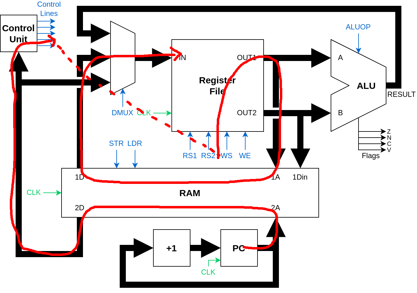
jp rd=mov pc, rd - Indirect jump
jp [rd]=ldr pc, rd - Sneaky arbitrary jump16
jp imm16=ldr pc, [pc+1]; imm16
- Register Move14
- Assigning a code to the zero register may seem like a waste, but it allows for many other instructions to be easily defined by abusing
- The zero register
- Uniformity of encoding: Instruction encoding is fixed-width, every instruction is stored as one word (16-bits). This means
- The machine code is easy to read, every instruction is exactly 4 hex digits long.
- We need not consider how much memory to read for the current instruction.
- Machine is easy to design with single-cycle execution.
- Single cycle execution: Each and every instruction executes on the rising edge of the clock, and takes only one clock cycle to execute.
- The decoder is relatively simple to design
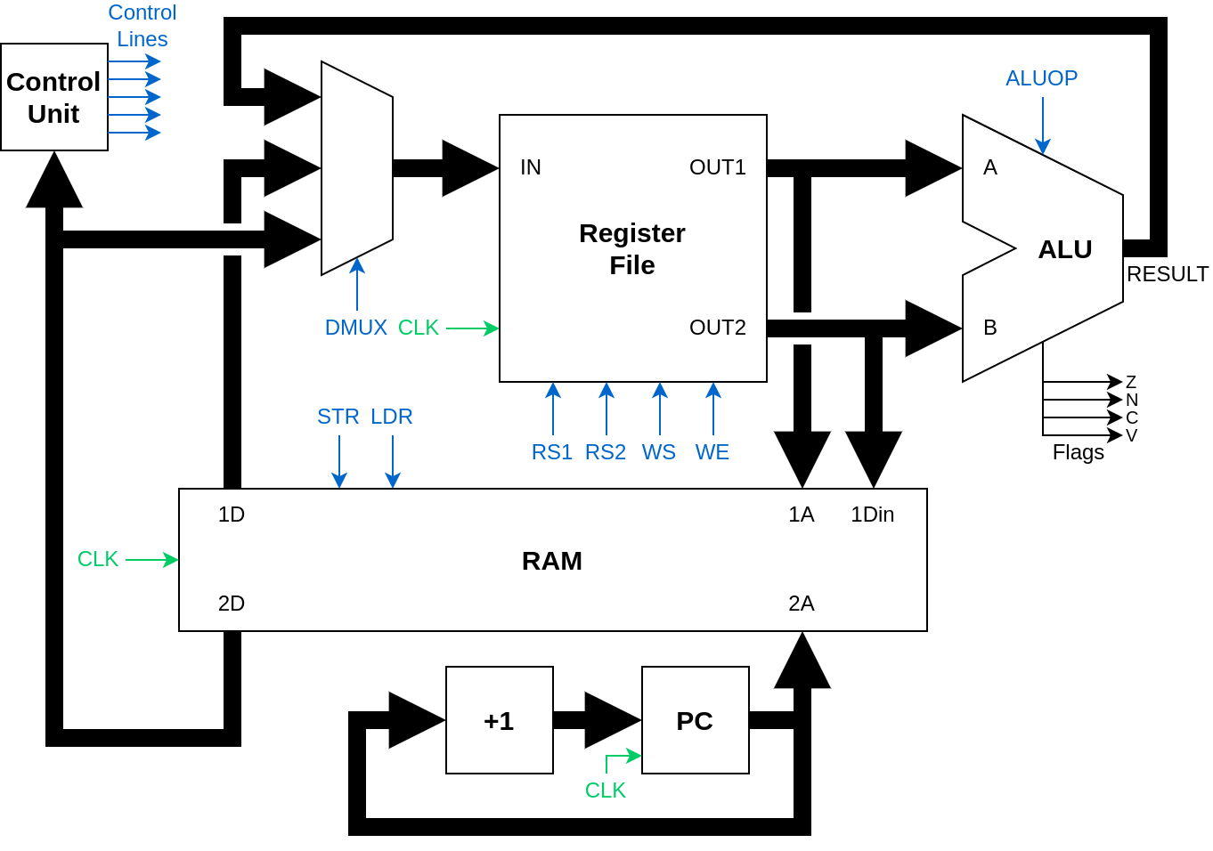
- In a more typical design, each instruction would decode as several microcode instructions, which are stored in a microcode ROM (or the control unit itself would have state). The CPU would contain a sequencer (a ring counter fed by the main system clock) that directs the machine whether to fetch, decode or execute. We dodge this entirely: the control unit is stateless, and directly maps from the instruction to the control signals.
- This did require telling a small white-lie and using a magic “dual port” RAM block, that allows for reading from one location, while reading/writing to another, on the same clock edge, which was an acceptable compromise from reality (the design is in the CPU, not in the RAM!).
- The decoder is relatively simple to design
- Assembling is easy: The ISA is simple enough that assembly can easily be mentally converted to machine code, and with little effort the machine code can be directly read as if it was assembly.
- Nibble aligning the register codes did the trick here, you only need to memorize the op-code for each instruction, and the encoding of the operands is obvious.
- It also gives a very obvious correspondance between assembly and the assembled machine code.
- Modularity: The CPU should be clearly divisible into separate parts that can be designed and tested in isolation before being brought together. To ease design, sequential17 circuits should be avoided as much as possible unless they are required for operation. To this point, only the register file is sequential, whereas the ALU and control unit are purely combinational18 circuits.
- Building the register file and the ALU are seperate labs, with their own tests, so we’re not building a CPU atop potentially faulty components
- The control lines are manually controlled at first to motivate their use, and only after that are students asked to design the control unit. This requires decomposing an instruction into the effects on the control lines, but doesn’t require something as complex as a sequencer or microcode, which we wanted to avoid.
- Avoiding a sequencer also means that the control unit is also purely combinational, and we have few enough control lines that it can be exhaustively tested and shown to be provably correct.
Course Design Principles
The core design principles of the course were:
- Pedagogy over realism, hardware over software: If violating standard CPU design or making the ISA more annoying to write assembly for meant the hardware implementation was easier, that was what was prioritised.
- The exact ISA encoding was changed several times over, as in through constructing the control unit, I would often find a simplification that could be made if only the ISA was slightly different, and then retroactively making the change. The benefit of this is that building QuAC is suspiciously elegant: Everything nicely fits together, and the logical expressions for each control signal simplify like a maths assignment rigged from the start so nice numbers pop out at the end.
- The critical data path is extremely long as a result of enforcing single cycle execution. This is fine, as now there’s plenty of bottlenecks to talk about, which motivates pipelining.
- Liberal use of abstraction: A circuit is designed, put in a box, and then the box is used to build bigger circuits.
- Individual components can be tested in isolation, and then once trusted, encapsulated in a box and treated as atomic.
- The best example of this: the register file has 6 level of nested abstraction:
- Logic gates -> SR Latch -> Gated SR Latch -> JK flip-flop -> JK flip flop with enable = register -> Register file
- The first lab drives this point home: Using gates to build a 2 input 1-bit multiplexer, and then extending to 4 input 4-bit multiplexer with liberal use of copy-pasting the base multiplexer.
- No magic anywhere in the machine: Every single component of the CPU is either a logic gate, or a circuit comprised of components. While large parts of the final machine use pre-defined black boxes (adders, registers) for the sake of integration with the simulator used, each black box is constructed at some point during the course, and in principle the black boxes could be avoided so that every gate is visible while the machine operates (though the simulation would obviously be rather sluggish).
- Data is code, code is data: The machine is a von-Neumann design. The program memory and the data memory is the same memory, and can be arbitrarily written to at will (allowing self-modifying code). Obviously, we wouldn’t want this for a real ISA, but for one designed for teaching, this opens up a lot of teaching opportunities.19
- Necessity is the mother of invention: The base ISA as provided is deliberately painful to write code in. This was by design: motivating students to extend the CPU to add features that make it easier to deal with. Some extensions20 fit perfectly into the existing ISA table21.
- There are only four general purpose registers.22
- Lack of an easy way to increment or decrement a register.
- No clear way to jump to an arbitrary address without clobbering a register in the process.
- None of the ALU instructions allow immediate values.
- This makes incrementing/decrementing annoying, as well as bit masking, as an additional instruction is wasted clobbering a register to load the immediate value. If you want to do
add r1, 1you have to domovl r2, 1 add r1, r1, r2instead, destroying the contents of
r2in the process.
- This makes incrementing/decrementing annoying, as well as bit masking, as an additional instruction is wasted clobbering a register to load the immediate value. If you want to do
- Explicit stack is missing, no instructions allow for calling/returning functions.
- A stack can be emulated in software, but requires all stack operations to be handled manually, as well as losing a register to act as stack pointer.
- Deliberately, no calling convention is provided either. Students can design their own if they wish to add function calls.
- No base+offset addressing, so
ldr r1, [r2+4]requires an additional instruction to load the offset into a register first (and then clobbering that register in the process). - No interrupts.
- No I/O.
- No exception handling. The behaviour of executing an instruction not defined in the base ISA is undefined.
- This means that the behaviour of an undefined instruction can be chosen to be whatever makes the hardware easiest to build.
- No logical shift/rotate or dedicate bit testing instructions.
- This makes bit manipulation as well as multiplication awkward.
- Can only conditionally execute on the zero flag.
- The spec is as permissive as possible:
- The machine can have any behaviour for an undefined instruction, allowing a lot of freedom to simplify logical expressions for the control unit using Karnaugh maps.
- Writing to the flag register (
fl) is undefined.- Makes the base implementation easier, don’t have to worry about anything else writing to the flag register other than the flags from the ALU.
flcan be extended to be made general purpose (presumably ifflis the destination register, this takes precedence over whatever the flag signals were generated), giving you more room to work with if you don’t care about flags, or it means the register code could be shared with a write-only register (maybe some sort of output device?)- Can define writing to
flin some wacky way: Maybe it truncates and writes to the top 12 bits only, preserving the flags? Maybe it performs some intermediate calculation before doing so?
- The top 12 bits of
flare undefined to read from (meaning reading fromflis possible, but the upper 12 bits could be any value.) This means we can hide all sorts of stuff in those 12 bits without breaking backwards compatibility:- Extra flags or status bits
- parity, exception handling, interrupts?
- An extra place to hide intermediate values for complex instructions like
mulordiv? - Can hide a 12-bit stack pointer there, and save the last register code for something else?
- Status bits that radically change the behaviour of the machine. It would be within the letter but not the spirit of the spec to have one of the bits in the flag register mean the entire ISA is interpreted differently, or extra hardware is enabled.23
- Shadow registers?
- Memory paging?
- Put the CPU into supervisor mode where values can be manually poked into registers via auxiliary inputs?
- Enable interrupts?
- Enable multi-threaded mode?
- Extra flags or status bits
Regrets
I have few regrets for the design decisions that were made, and am happy with the trade-offs that we did do, but there are a few things I wish we had chosen differently.
- Undefine a large block of address space, leaving room for special reserved memory addresses that can do neat hardware things.
- This can still be done, so long as the memory can still be written to and read from like normal memory. Allocating a block of memory for a framebuffer linked to a screen is legal, so long as you can still use the framebuffer as generic scratch memory.
- The one thing you can’t do (which I regret) is allocate off a block of memory for a ROM that allows some sort of bootstrap program to run on boot.
- The use of a word (16-bits) as the smallest addressable unit.
- At the time I advocated pretty hard for this (it makes single cycle execution easy and it simplifies a lot of problems with decoding), but it loses an opportunity to teach about endianness.24
- How do you put a string into memory? Do you pack them in two characters in a word? Or does each character receive it’s own word?
- What would be more ideal would be to have memory banked into two chips, each with capacity 64 KiB = \(2^{16}\) bytes. One stores the high byte (called HRAM) and the other the low byte of memory (called LRAM). When fetching an instruction, we feed
pcto HRAM andpc+1to LRAM25, and thenpc := pc + 2after every instruction is successfully executed. Every instruction then occupies exactly two bytes in memory.- This means you can ask fun questions like “what happens if we load from an odd-numbered address?”
- You can also then write separate
ldbandldwinstructions that load just a byte, or a full word. - It halves the amount of memory from the current design from 128 KiB to 64 KiB, but who cares, nobody was going to use anywhere near that much memory anyway. If they were, they can add memory paging as an extension, or some magic instruction that uses two registers together to address 32-bits, or something like that.
- Having the machine start executing from memory address
0x0000.- It’s common for old-school machines to do this, but given the annoyance of jumping to addresses outside the range
0x0000-0x00FFit’s common to have an interrupt vector table or other special reserved memory there, and/or forbid interaction with memory address0x0000to allow for null pointers. - Often the first instruction on old machines is to jump over the interrupt vector table. I think we can just do the same here.
- It’s common for old-school machines to do this, but given the annoyance of jumping to addresses outside the range
- Not having a clean way to jump to an arbitrary 16-bit address while adhering to single-cycle execution, and fixed length word instructions.
- Currently, to jump to memory address
0xABCDin the base spec, the obvious thing to do ismovl r4, 0xCD seth r4, 0xAB add pc, rz, r4 ; move pc to r4which is unsatisfying (takes three cycles, and clobbers a register). Perhaps it’s fine leaving it like this, as it can be fixed in an extension.
- Currently, to jump to memory address
- In general, loading an arbitrary 16-bit address into a register is awkward.
- Maybe that’s fine, it’s awkward in lots of ISAs (you usually have a psuedo instruction that puts the immediate value somewhere special in memory, and reads it out.)
- Currently the entire bank of instructions
0b0000 x000 xxxx xxxxexecute as ano-op(do nothing). This is wasteful. The spec should be redefined such that:0x0000encodes theno-opinstruction.0b0000 0000 imm8for allimm8 != 0x00is undefined0b0000 1000 imm8for all imm8 is undefined.
It changes nothing for implementing the base machine, you can just treat decode
0000 z000 <imm8>asmovl{z} rz, imm8as you currently do, and that would be within spec, asmovl rz, 0x00is anopanyway. There’s no reason you’d ever want to move an immediate into the zero register other than to waste an instruction cycle (it has zero side effects, flags are unchanged, ect.). This is often useful26, but we waste the other 511 instructions of the form0b0000 x000 xxxx xxxxon no-op as a result. This now gives you an extra 511 unconditional zero-operand instructions, or another 255 conditional zero-operand instructions, or some combination of instructions with operands if you want to subdivide the imm8 region further. This could add things like halt execution, enable/disable interrupts, call, return, ect.
-
I think the lectures briefly talked about how to build NAND gates from CMOS transistors, and often you want to make use of tri-state buffers/high-Z state for CPU designs that are instantiated in reality, and that HIGH/LOW is just an abstraction as the voltage at any point in a circuit is a continuously varying voltage, but we abstract all that away, and assume that logic gates are zero-delay, infinite input impedance, zero output impedance, infinite fan out, perfectly ideal components. If ever a node is simultaneously driven to both zero and one at the same time, the digital logic simulator gets upset and throws an error. In real life, depending on what your logic gates are constructed from, you could get an intermediate voltage as the components form a voltage divider over the wire linking the low to high point, or more likely, a lot of angry electrons would flow until one of the components along the chain gives up the ghost and pops, flooding the room with magic smoke. ↩
-
Quarel-Akram-Connor, after the codesigners David Quarel (me), the convener Shoaib Akram, and Jon Connor, the other head TA for the course. Gotta make a legacy somehow. ↩
-
What we ended up with would be pretty monstrous to actually construct physically, either from a truckload of 7400-logic ICs or worse still, from transistors. (The liberal use of several 16-bit multiplexers really adds to the gate count). However, assuming an ~infinite supply of gates, and the ability to construct a circuit from gates, wrap it in a box, and abstract the insides away, this CPU is very straightforward to construct either in a GUI logic gate simulator, or in some HDL for an FPGA. ↩
-
Sacrificing an entire register to always be zero might seem expensive, but this allows for a slew of pseudo-instructions like
mov(register move),cmp(compare) andjp(jump) to be defined as a special case of existing instructions. ↩ -
The reason why writing to the flag register is undefined is to make the base ISA as compatible as possible with extensions, as well as make the implemention easier. You might decide that writing to
FLhas no effect, or that it can be written to like any other register. Both are compatible with the spec. You might also want to define a meaning for the other bits in the flag register (usually called control bits), and the CPU behaves differently depending on the value of those bits set by the user. ↩ -
This allows for the synthesis of many other instructions. For instance, we can use the following code to skip over a small piece of code.
movl r2, 2  ; r2 := 2
add pc, r2  ; pc jumps two addresses forward
movl r1, 1  ; this instruction gets skipped
movl r3, 3  ; this instruction gets executed
Or (stranger still) to load the machine code of an instruction itself, and use it as data
ldr r1, [pc] ; r1 := 0x5710 -
Though there’s nothing stopping you from adding extra formats for new instruction when you extend the ISA. ↩
-
All instruction in QuAC except for
strwrite a result to a destination register, except forstrwhich usesrdas the data to store to memory. While a little confusing, this makes the implemention in hardware a bit easier to deal with. ↩ -
You may want to define a meaning for the reserved bits when you implement an extension to the base ISA. ↩ ↩2
-
Though you may allow this if it makes implementtion easier for you. ↩
-
This matters for conditional execution. Executing
addz r1, r2, #2should have no effect on the flags if theZbit in the flag register is cleared. ↩ -
This also allows for the opportunity to have writing to the zero register to have some additional stateful effect, that extension instructions could interact with. Of course, base instructions couldn’t have changed behaviour, as this would violate backwards compatibility. ↩
-
Turns out this is also relatively unorthodox, and while it means you can do silly shenanigans with the control flow of a program, it is a nightmare to resolve the additional pipeline hazards. Whoops. Normally,
pcdoes not receive a register code, and can only be modified by special instructions (jump,call,retetc). This also consumes an additional register code, but the teaching moments it gives are worth it. ↩ -
With the annoying caveat that these psuedo instructions are technically ALU operations, and would tamper with the flags. ↩ ↩2
-
I think it’s good practice for the instruction with machine code
0x0000to benoporhaltor throw an exception or something along these lines. ↩ -
Assuming the
ldrinstruction is extended to allow for offsetting by an immediate (or at least offsetting by one). This is very much a dirty trick, as we’re essentially shoehorning a multi-word instruction into a machine that has fixed-width instructions. The instructionldr pc, [pc+1]loads the value of the next memory slot and overwritespc, and the next value in memory just so happens to be the address that you want to jump to! This dodges the problem of designing an instruction that fits in 16-bits, while also allowing an arbitrary jump to any 16-bit address. ↩ -
The behaviour of the circuit depends both on the current input, and some hidden state inside (implemented as feedback loops inside the circuit)27. ↩
-
The behaviour of the circuit is a function only of the current inputs, allowing for ease of testing as (assuming the input space is not too large), one can exhaustively search the space of all inputs to provably show the circuit is correct. ↩
-
Turns out this plays havoc with anyone trying to build a pipelined version of QuAC, where it is assumed program memory and data memory are separate. It’s hard enough to pipeline with shared memory, let alone when self-modifying code is a possibility. My apologies to those in COMP3710 who were tasked with this. Whoops. ↩
-
No, I won’t tell you which! ↩
-
Almost as if they were present in an older prototype of QuAC, but were stripped out to make the base ISA easier to implement. ↩
-
In retrospect, would it have been better to go for an accumulator based design? It would have still maintained the other design principles, but then it would have been harder to transition to the second half of the course, which uses ARM (and has general purpose registers galore). ↩
-
You could have one of the bits mean “interpret all the instructions as if they were x86” or some other unhinged ISA, and then have a secret instruction that sets that bit, and then the CPU is now an x86 emulator. This would be a terrible idea, but it’s within the rules of the spec. Don’t do this. ↩
-
I’ve also been told it makes it difficult to write a compiler that targets QuAC, as most tooling assumes byte addressable memory. ↩
-
Or
pc+1to HRAM andpcto LRAM? ↩ -
Why have no-ops? Most of these use cases are for real world machines: They’re useful for padding out a program to align to a certain memory boundary if that’s required, introducing a deliberate delay in the execution of a program (when you’re waiting for an I/O device or slow memory to respond, or you’re trying to bit bang a particular signal from an I/O port.) If your machine is pipelined, you sometimes need to stall the pipeline to avoid a hazard, and so the computer needs a dedicated instruction for no-op. They are also useful for avoiding timing attacks where you can work out the execution of code based on the different times it takes for different branches to run, so you can dodge this by padding out the fast branch with no-ops. In the case of QuAC, we only use no-ops as by default each word in memory is initialized to
0x0000, so it’s nice for the computer to do nothing when it encounters uninitialized memory (for a more realistic machine, halt and raise an exception would possibly be more useful, as you know when you’ve stumbled into uninitialized memory), and it’s probably useful for many extensions of the base QuAC ISA to have already existing no-op instructions. ↩ -
This implies sequential circuits have memory, and it makes testing difficult. In general, verification of arbitrary properties of any sequential circuit is impossible due to Rice’s theorem. Assuming a synchronous design, one can always factor a sequential circuit into two components: A transition logic block \(T\) that maps inputs \(x_t\) and state \(s_t\) to outputs \(y_t\) and next state \(s_{t+1}\) (and is purely combinational), and a state block \(S\) that on timestep \(t\), outputs \(s_t\) and stores the new incoming \(s_{t+1}\) (which is sequential, but does no other processing, and merely outputs whatever its input was one timestep in the past.) In this way, arbitrarily long time dependencies are possible, and for a specification that describes the full behaviour of the transition logic \(T\) (and assuming \(S\) is correct), the unit can be exhaustively tested. For any non-trivial circuit this is still intractable, as the state space is exponential in the number of bits of state. Even exhaustively checking the register file is intractible: with 6 registers
r1,r2,r3,r4,pc,flthat can store state, and with the fact that we only need to consider the lower 4 bits of the flag register, gives a total of \(2^{16+6} = 2^{22}\) bits of state. There is one 16-bit input and 4 control lines, so the total number of combinational transitions to check is \(2^{16 \times 5 + 4} \times 2^{16 + 4} = 2^{104} \approx 10^{31}\). For the full CPU this gets even more unlikely: with \(2^{16}\) words (16 bits) of memory, and (approximately) 6 registers that can be in one of \(2^{16}\) possible states, gives a total number of states for the CPU as \(2^{2^{16} + 6} \approx 10^{19730}\) states to check. Not likely. In general, the best we can hope for is a bank of test programs that puts the machine into every edge case we can think of (conditionally executing every instruction with and without success, and verify the instruction was executed correctly). Given the simplicity of the machine, it’s unlikely there would be a bug such that the machine would execute every instruction perfectly, but would fail when you execute a particular sequence of instructions unless you went out of your way to include such a bug deliberately. Of course, real machines are far more complex, and such bugs are common enough to have cost a lot of money to fix, and in some cases can even damage the hardware itself. Unlike software bugs, bugs in hardware often cannot be patched: At best you write some new software that would detect if the machine is about to enter a state that triggers the hardware bug and avoids it (often at a cost to performance), or at worst you have to recall the hardware at great cost. ↩